ZAM Badge - Cat with Knife
Überblick
A badge envisaged for ...
Projekt-Metadaten
Cat with Knife GitHub Repository
Schumi daniela.novac@betreiberverein.de
Steve Mayze smayze@yahoo.com
Logbuch / Schritte
Tag 1 Friday 07.02.2025
We discussed the design
[PHOTO of the model badge]
Tag 2 Saturday 08.02.2025
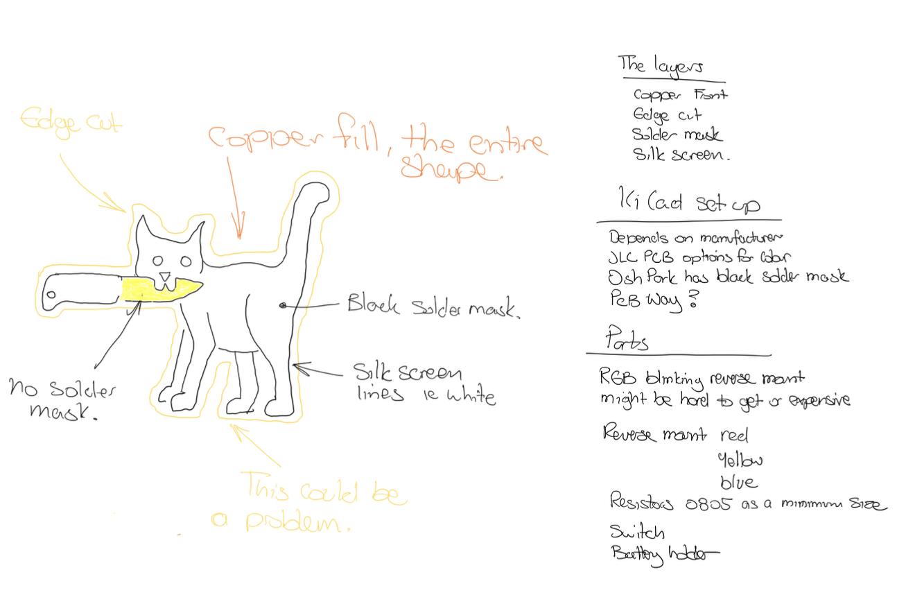
A PCB is made up of layers. These layers can be set up to create images or other effects such as to block or let light through. In the case of this project, the first requirement was that the knife blade needed to be metallic i.e. silver and that the eyes would glow. For any board the first and most important thing is the edge-cut. This layer of the design defines the outside boundary of the board. Ideally this needs to be 0.5mm bigger than the actual image itself as this will define the path that the cutting tool will make to create the board shape.
In the sketch below Steve put together some initial ideas on how he believed the layers should or could stack up.
Tag 3. 11.02.2025
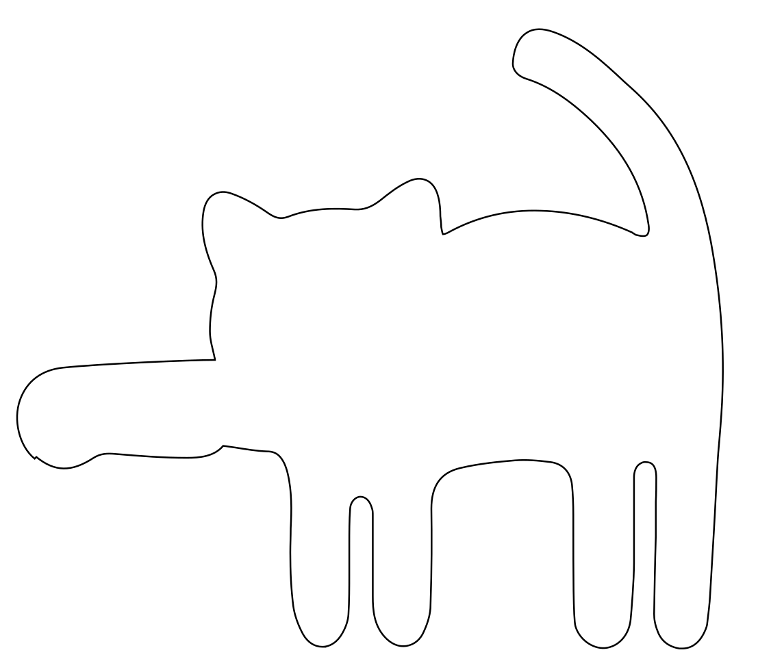
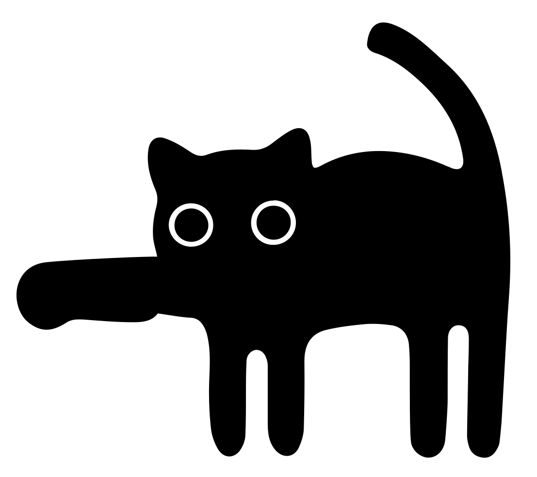
Schumi created the graphic files required - Edge Cut, Front Copper, Solder Mask, Back Solder Mask. There was a bit of going back and forth between Illustrator and KiCad to ensure that we could create the desired effect. Rather than having the eyes glow, the intention is to have the circle of the eyes glow. So for that we needed to ensure that there was no copper on both the front and back of the board where the eyes are. This effect could be created by modelling the eyes in the front copper layer.
|
|
|
| Edge Cut | Front Copper |
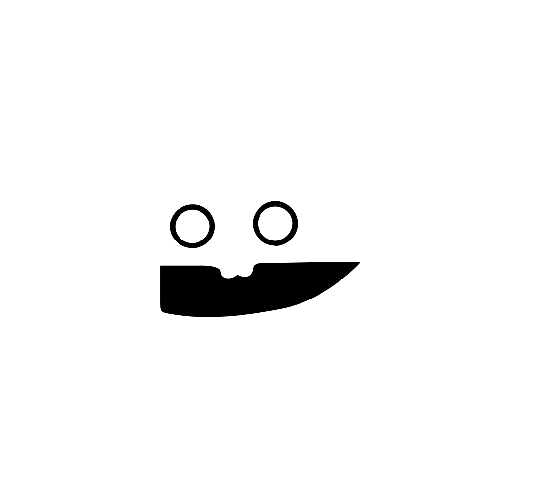
The font solder mask defines where the solder mask should not be applied. This then ensure that the board substrate layer will be visible around the eyes but will also ensure that the copper is exposed for the knife blade. During fabrication, the exposed copper will be coated with a solder layer. This will render the knife blade silver in colour.
The back solder make also defines where there is no solder mask. The PCB design will ensure that there is no copper also at this position, exposing the underlying board substrate. This then will enable light from the LEDs to shine through the substrate.
|
|
|
| Front Solder Mask | Back Solder Mask |

The size of the board dictated what type of parts to choose. i.e. the largest part was the button cell battery. The CR2032 holder size would not have fitted on the board and to use such a batter would mean having a much larger board size which will directly affect the cost of the project. Therefore the smaller holder for the battery series 1216, 1220 and 1225 was chosen. Along side the smaller battery holder, a small slide switch was chosen.
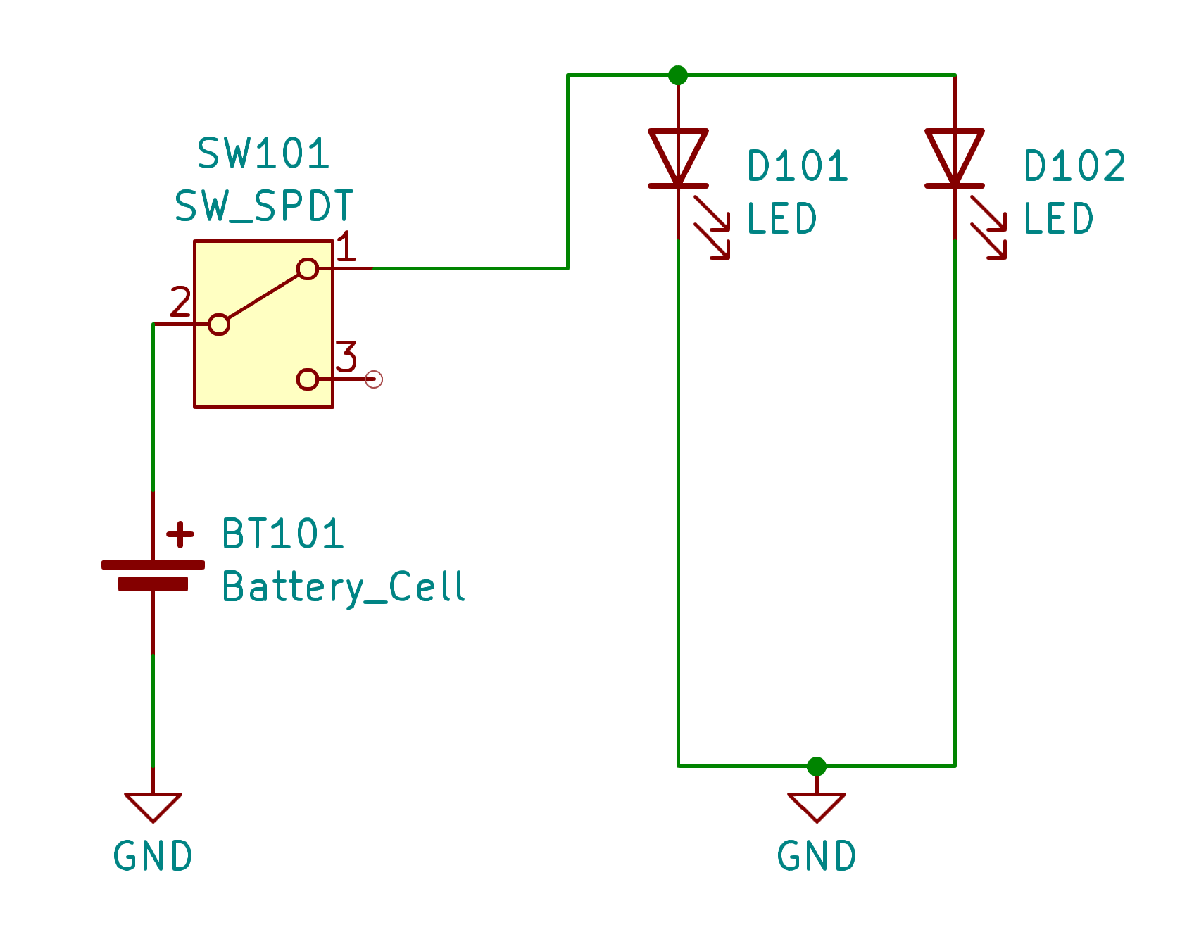
At first it was hoped to use reverse mounted LEDs but since the hope was for self-blinking LEDs this idea was not going to work. It was difficult to source such LEDs if they exist at all. It was then decided to use normal 3mm (or 5mm) self blinking LEDs. Using self blinking LEDs with such a small battery cell makes the design relatively simple. i.e. there is no need to provide any current limiting resistors.
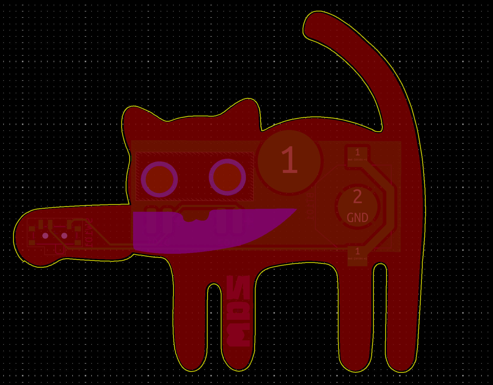
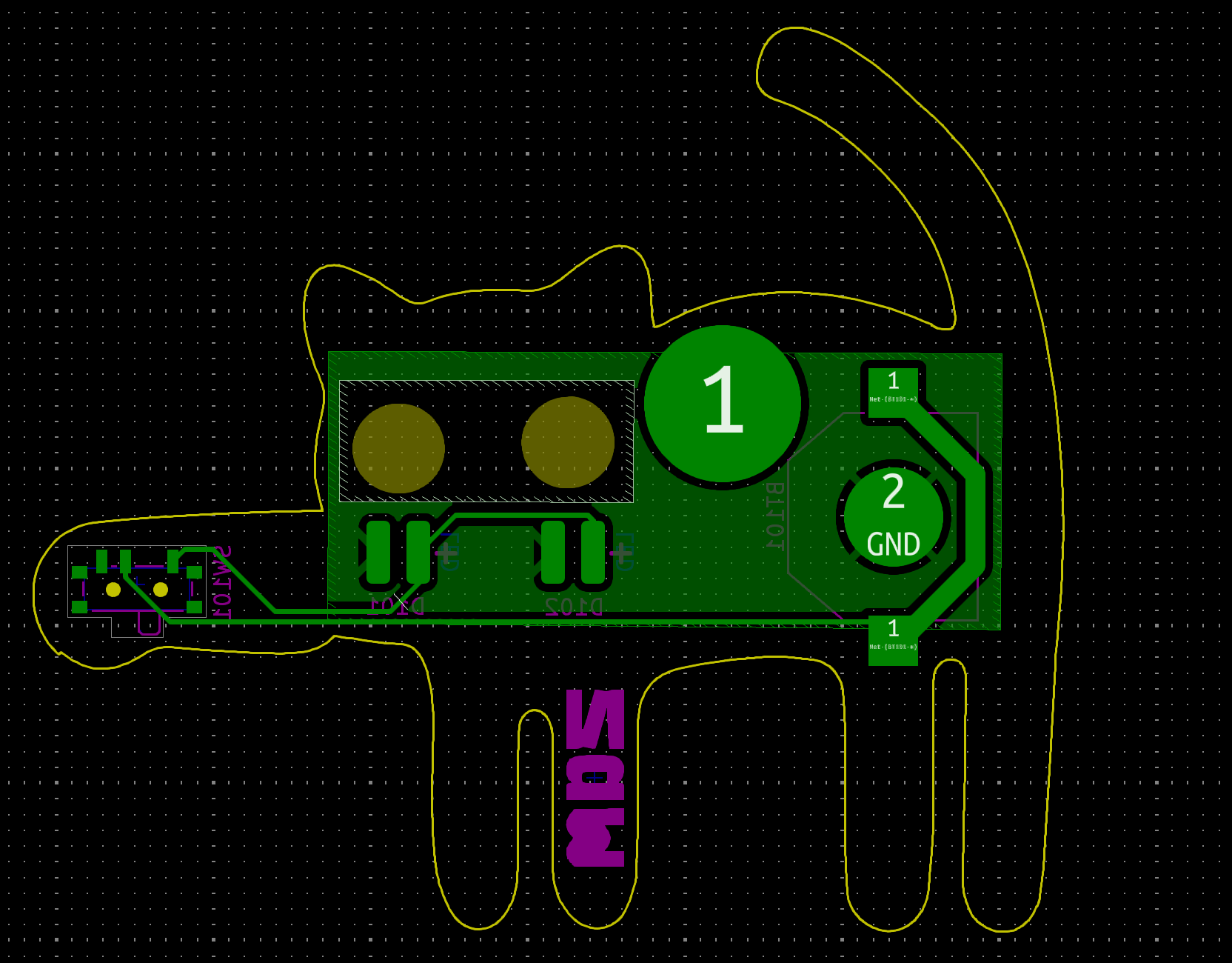
|
|
|
| PCB design with front copper pour | PCB design without the front copper pour, showing the back copper. |
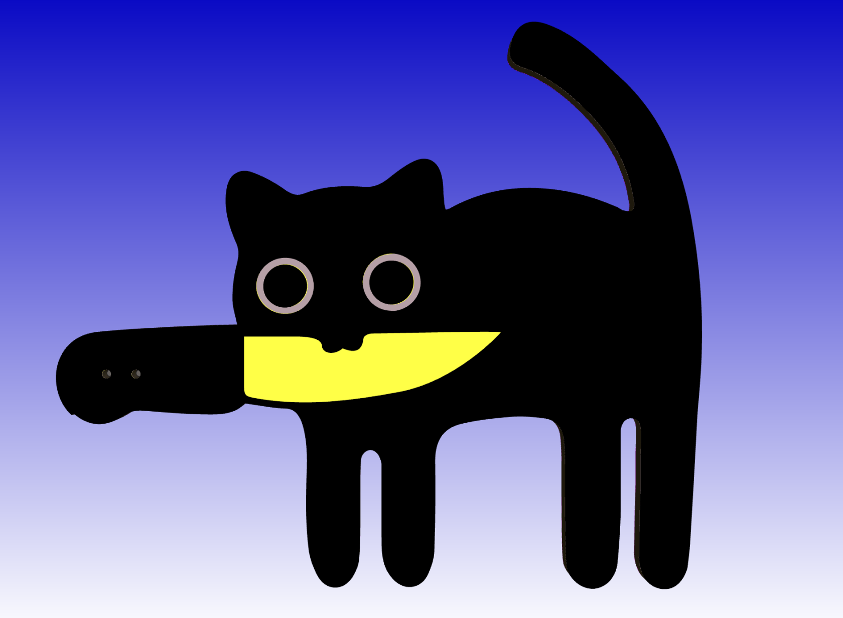
|
|
|
| 3D view of the final design |
3d view of the back side of the PCB |

The design files were sent ofoff for fabricationfabrication, 12.02.2025.selecting a board thickness of 0.8mm to maximise the amount of light able to shine through and a back solder mask to match the original badge colour.
